
Introduction
When we talk about desktop cockpit of an F-16, the MFDs, and ICP provide a way more immersive flight simulation experience, coupled with the Throttle and Stick, cover by far most of the Viper use during flight. The misc panel, on the other hand, simplify the handling of the aircraft when the pilot is preparing to combat or using the autopilot.
There are commands of the landing gear panel, which are definitely recurrent, such as the landing gear lever, parking brakes, landing lights, possibly store configuration. Nevertheless the landing gear panel provides also visual clues, as the downlock of nose landing gear, main landing gear, and the one in the lever, provide important feedback during takeoff and approach.
The panel is important, but possibly the real reason why I wanted to develop one, is that I always wanted to actually raise and lower a real lever to actuate the landing gear. For the design I used CAD, while the realization was possible only thanks to my mini (modded) CNC and a 3D printer.
This page will cover the components list, the design of outer case, landing gear lever box, and landing gear panel, and finally the assembly.
Design
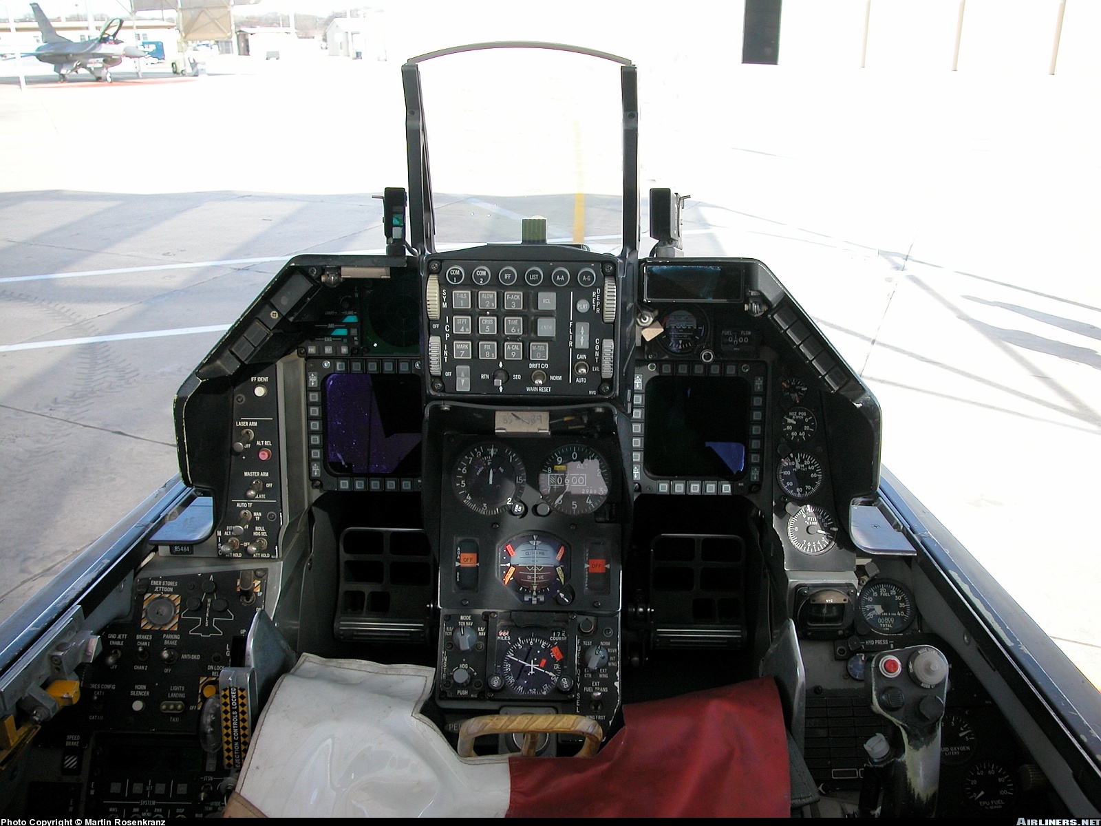
In the F-16 cockpit, the landing gear panel is placed in the center console, left hand side, below the miscellaneous panel. It is rotated by an angle of approximately 25°, and its side collides with the housing for the pilots left leg. The panel case in my pit will be placed slightly lower than the miscellaneous panel (but not under), and on its left. A rotation (possibly smaller) will be introduced, as due to the spacing and general dimensions of the components of the panel, without rotation the ergonomics are quite poor, many visual clues are shadowed, and accessibility of some switches is not optimal.
The concept is made of :
- the outer case (in MDF).
- the landing gear lever box (inside the case), to fit all the retraction extension mechanism.
- the panel (that will be screwed to the MDF), with its back light panel (3D printed), which will house all the switches (but the downlock release and landing gear lever) and most of the backlight leds.
Outer Case
The outer case is rather simple, I mostly used MDF, with few 3D printed insertions. everything was glued together with wood glue.
The opening in the front is built in a way to allow inserting the Landing gear lever box. The panel is then screwed in place. Two holes were drilled, one for wires access and the other to install the led back-light switch. The top is covered with a black sheet of ABS (1mm thickness).


Landing Gear Lever Box
The landing gear lever box, is by far the most complex part of the whole assembly, the design of the cam-spring feedback required quite tight tolerances, and in my case was possible only thanks to 3D printing.
The mechanism relies on a cam-spring joint, which provides a (small force) feedback on both directions (up and down). I chose to use a spring mechanism, as elastic bands severely degrade during years/use, spring are more reliable under that perspective.
The lever position up and down is sensed via two (one could be enough) limit switches. The lever is held in place via 2 12V electro-doorlocks, which are disengaged when the button on the lever is pressed.
Since the electro-doorlocks rely on solenoid, and are powered with 12V, they create quite a lot of interference on the line for this reason I installed two fly-back diodes.
Rotation about all the axis of the landing gear lever box is provided by means of chicago screws.
The lever was designed with embedded wires housing, to so to provide a convenient place to feed the two red leds on the cap, and the button which activates the electro-doorlocks.


Landing Gear Panel
The front panel with the engravings is stiffened by a 3D printed support, which houses the backlit leds, as well as the switches, and buttons. In order to give room to the screws, the 3d printed support is quite smaller with respect to the landing gear panel. This shape mismatch is suboptimal as far as back lighting is concerned.
The 3D printed support holds the satellite pscockpit.
The pinout of the board is as follows:
- Hook Release Switch
- Nose Landing Gear Led
- Right Landing Gear Led
- Left Landing Gear Led
- Emergency Stores Jettison Button
- Parking Brake (3 way switch)
- Anti Skid (3 way switch, Parking Brake)
- Ground Jettison Enable Switch
- Landing Lights (3 way switch)
- Taxi Lights (3 way switch)
- Horn Silencer pushbutton
- Stores Configuration switch
- Landing Gear Lever Led
- Landing Gear Up limit switch
- Landing Gear Down limit switch
- Downlock release pushbutton
Given the pinout reported above, at this time the brake channel 1/2 is not wired, the reason is that in Falcon BMS is still not implemented, there is room either to unwire the anti-skid (which is not implemented as well), or taxi lights. In principle, wiring in parallel the landing gear up / down limit switches could do the trick as well.


Components needed
The complete list of the needed parts is rather long:
- 1 16 I/O psCockpit expander.
- 3 2 way switches.
- 1 short 2 way switch.
- 2 3 way switches.
- 1 small pushbutton switch.
- 2 pushbutton switches.
- 1 big pushbutton switch.
- 3 green leds with stainless housing.
- 2 red leds.
- 2 limit switches.
- 20 green leds.
- 23 120ohm resitors.
- 2 diodes.
- heat shrink isolator.
- 1 spring.
- 2 small Chicago screws.
- 2 medium Chicago screws.
- 1 long Chicago screw.
- 12V Powersupply (to feed the electro-door locks).
- 2x 12V electro-door locks.
- 4 MDF sheets (5 mm thickness).
- 1 ABS black sheet (1 mm thickness).
- Several 3D printed parts ( landing gear lever, CAM, landing gear lever box …).
- a lot of wires.
Assembly
PLA (3D printer filament), and MDF where glued together with wood glue. Most of the parts were screwed together, to allow disassembly.
For the outer panel (and for the landing lights switch cover), spray paint was used, a primer was used on the 3D printed part then the final color was sprayed directly. The final result is way better with respect to conventional brushed paint.
During assembly I tried to add yellow paint to the dashed squared of Emergency Jettison, Hook Release, and downlock release, unfortunately the results was not as expected, therefore I kept the original black-white panel.


Software interface
Once assembled the board shall be physically connected to the PSCockpit Mainboard, and interfaced with the PSCockpit software (which links it to the simulator). The interface with the mainboard is made through 5 cables (5V, GND, INT, SDC, SCL). The configuration of the PSCockpit software is pretty straightforward. Please have a look to the PSfalcon blog:
The first thing to setup is the PCB I/O layout, then once the correct input is wired, the PS Command page shall be filled with the keystrokes that PSCockpit will send to Falcon BMS to mimic the function (obviously consistent keystroke shall be configured in Falcon BMS). Particular attention shall be made to the Emergency Stores Jettison pushbutton; in order for it to work properly, the option Hold Key must be selected, and the keystroke must be filled for both the ON and OFF columns. Finally, through the F-16 model page, it is possible to assign the right output to the specified Pin (e.g. pin 0, 1, 2 are respectively assigned to LDG Left, Nose, and Right Green led light).


Final Result
As usual, please find a comparison between render, and the final result.


…and a shot of my pit !

3D model repository
You can find the 3D model (STL) of the landing gear lever box here.

Great work! Are you planning on sharing STL files for the gear know and lever?
Dear Jussi, I’d like to understand whether the device can be in some way manufactured even in small numbers, therefore, at the moment I don’t foresee sharing the files, in case I don’t manage to do it, I’ll share them for sure
Well, after all I decided to share the STL files, you can find the link above !
love your work. I was inspired by your solution using solenoids, but I’m suffering from a lot of interference. I already put the diodes, but they continue to impact the switches that trigger the gear, landing lights and others. Interference occurs both when triggered and not triggered. Could you help me? tnks
In general I’d suggest to shield the line ( as there may be interference despite the use of the diodes), also the diodes shall be as close as possible to the solenoid, and wired correctly, you may also test them to check whether they are ok. What do you mean with the fact that they impact the system also when not triggered? I had once a similar problem and it was a faulty soldering. If you disconnect the solenoid does the issue persist?
Hello, I’m going to shield the line. The diode I put only one, going from negative to positive next to the source plug. I’m going to change and put one on each solenoid going from the negative wire to the positive. Thanks for the tips, I’ll send a photo of the work done later.