
The Radar Warning Receiver (RWR) in the Viper cockpit, and in any modern combat aircraft, is a vital system, it provides situation awareness on the surrounding threats to the pilot.
The Threat Warning Prime (TWP) is an utility panel placed just to the left of the RWR display which provides easy to reach functions and submodes for the RWR system. It is composed of 6 buttons in an “half pyramid” configuration: in a sequence of 3, 2, 1, starting from the bottom.
A full description of the functions of each button can be found in the very well written and detailed Falcon BMS documentation (TO-BMS1F-16CM-34-1-1 : Flight Manual, alternatively xflight.de provides an insight), and therefore is not reported here. The six buttons power the RWR, control its submodes (Low Altitude), run the system test, and warn the pilot in case a missile launch is detected. I chose to put the panel on top of the left MFD, so colliding partially with the LCD, therefore I went for a compact design, relying on the Hispapanel panel (and button labels), and PSFalcon PCB.
The PCB can mount RAFI-15 backlitted pushbuttons, and enables to have a compact assembly, only 13mm thick.
Post outline
- Components
- Preparing the pushbuttons
- PCB
- SMD soldering
- Panel
- Assembly
- Interface
- Integration with the cockpit
Components
I chose to buy COTS for this panel so I purchased:
- Hispapanel TPW panel
- 3D printed spacer layer
- 3D printed back case
- 6 RAFI-15 pushbuttons (purchased from Hispapanels)
3mm cyan leds- 3mm green leds
- 3mm red leds
PSFalcon TWP PCB- A custom designed TWP PCB
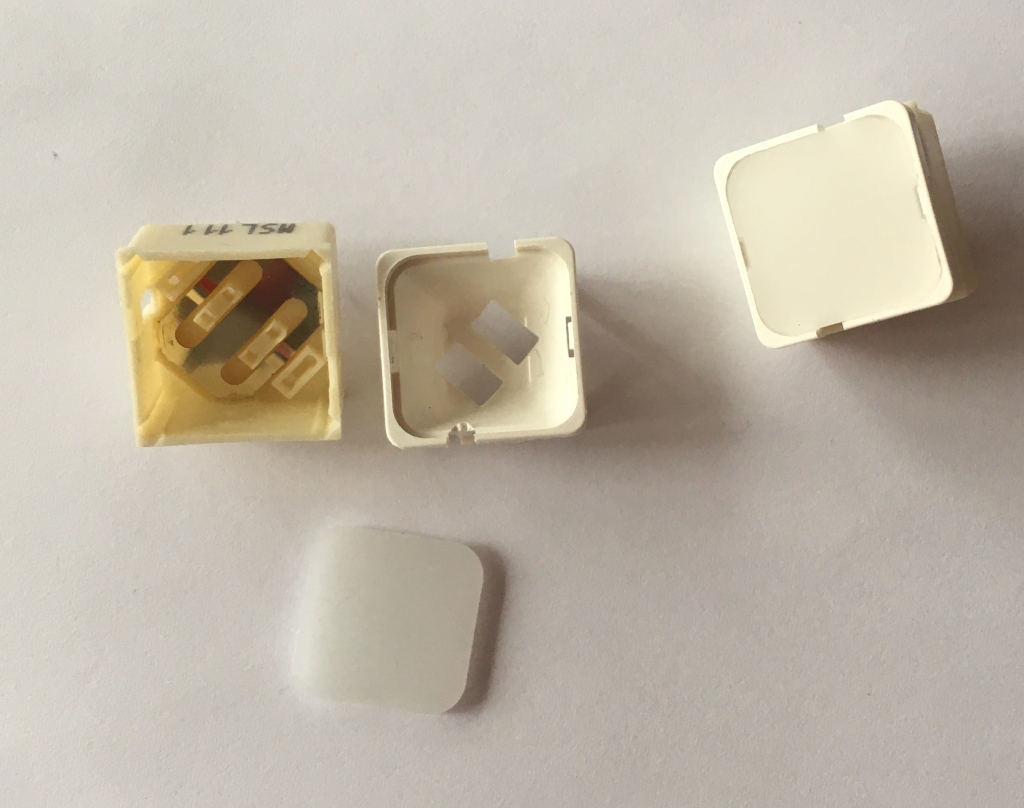
To close the panel, I 3D printed a case, that has also the function to connect the assembly to the Left MFD/LCD.
Preparing the pushbuttons
Hispapanels panel is designed to fit the RAFI-15 push buttons. They can hold 2 leds, therefore is a perfect choice for this panel.
The pushbuttons are a German design, very well manufactured, but need some preparation so to fit perfectly for the purpose. The first and most noticeable, is the color, the white/cream color isn’t the best match for a modern era cockpit. I hand painted them using Vallejo Black paint.
Second task is to separate the led housing, so to allow differential led lighting (usually top/bottom). For the purpose, I created a simple separator and then 3D printed it, as always with the Cura Slicer.


Last but not least, the pushbutton covers. I purchased hispapanels labels, which are great, but need a final touch to really have the best result. The labels, are basically transparent acrylic, black painted on one side. Both sides are engraved, which results in easy to read back label (the one which will be back lighted), but the front side is simply scratched (engraved, more specifically), and the text string is not easy to read, even with an high contrast material on the back. If it was a dark button, it would be even more difficult. Therefore I painted (with a white marker) the labels, and removed the exceeding paint with alcohol. I also added a couple of layers of invisible tape on the back, so to diffuse the backlight. The result is that the labels, which are not meant to be back lighted, are much more easier to read. The pictures that follow illustrate the effect (before, on the left, after on the right).


Once the labels are ok, I painted black the RAFI-15 buttons, so to have an assembly better fitting the Home Cockpit. Then I prepared the holes in the buttons bases so to properly install the standard 3 mm leds.
To complete preparation of the Rafi buttons, I used a mouse to remove 1 mm to each led, so to avoid interference between the led and the Rafi button label, when the button is pressed. To secure the 3d printed separator to the internal of the Rafi button I hot glued them. Finally, I soldered the buttons to the board and the leds, and installed the labels.

Another interesting feature of the hispapanel is that it comes with several layers (in this case 2), the second layer fits tightly the RAFI buttons, so that basically once you solder them it is impossible to remove the panel layer. This is quite annoying from a maintenance standpoint, I think the choice was to have zero tolerance to prevent any backlitting “escaping” to the surface.
PCB
I purchased the great PSCockpit PCB, but had some problems integrating the buttons. Basically the problem was that the (internal) LED holes didn’t match with the PCB holes.
For this reason I designed a PCB to suit my purpose, I did with easyEDA, which provides a great integration with the jlcpcb website. The board integrates in the PSCockpit environment (I also took care to assign the same pinout as the original TWP board, so to avoid any hassle in the configuration). It has 40 I/O, with the common address switch so to populate in a daisy chain fashion the MainBoard channels, a BIT led, to check whether the board is powered, and a backlight circuit, to highlight the TWP label. The board is compatible with Hispapanel TWP. I tried to keep everything as low profile as possible, and moved as possible all the components upwards, so to have the most space in the lower part of the board, where the geometrical interference with the MFD is most likely.
In easyEDA I had to design also a component (the RAFI15H pushbutton, and its pinout and footprint), have to think about the possibility to write a simple post with the lesson I learned throughout all the process. Bottom line is, jplpcb provides a great service and allows to have at a reasonable price, prototype PCBs, with also SMT service (surface mount)!
I finally chose to purchase the boards painted Black, so to reduce as much as possible any contrast with the rest of the panels, and case.


I used the rather common 2.54 mm spacing Duponts connector.

SMD soldering
As you may noticed, I purchased the PCB with SMT, so basically it comes with already pre-installed components (black resistors). Unfortunately JLCPCB didn’t have stock for the Microprocessor, which is by far the most complex component to solder.
In order to solder it, which, by the way is only 14×10 mm, per 56 pins! I took advantage I a digital microscope, 600x. To be honest I was quite skeptic about the possibility to solder SMD by hands. That’s the reason I purchased the micro.
By the way, by reading a bit online about SMT and by using good soldering wire, flux, and the right temperature (330°C work pretty nice with my setup), SMT was surprisingly easy to do.
To solder it I used the drag soldering technique, basically it relies on using a fairly big soldering tip (with respect to the pins), of C type (the one with a 45° chamfer), add a bit of flux on the pins, gently slide the tip across the pins, and let the flux do its magic. I had to remove a bit of tin excess by using wick, but only on a couple of pins.
As the flux leaves the board quite dirty (and its components may even corrode partially the tracks), I finally cleaned it by means of alcohol (isopropyl alcohol would be better) and chem wipes.
I used a fairly similar process to solder the backlight LEDs, with the exception of the soldering itself where I used the standard point soldering, instead of drag soldering. Being the LEDs ultra small components, the microscope was very useful to identify anode / cathode and align them properly with the aid of some tweezers.


Panel
HispaPanels are great, but the TWP comes with 2 layers of approximately 3 mm each, therefore the RAFI 15H buttons will stand out few mm. In the real panel, as far as I can tell looking online, the buttons are sort of flush mounted with respect to the marker. It does make sense so as to avoid any undesired press.

For this reason I designed a simple part (easily 3D printed, but could also be CNC machined). The layer raises of 3 mm the Hispapanel, so to have the buttons flush mounted. The slot on the bottom is meant to allow the backlight leds to light the TWP label.

Assembly
With the panels and board, the only missing part is the back of the case, as well as a way to firmly connect it to the MFD. For this purpose I designed a custom case, to be 3d printed.
Therefore I also modelled and 3d printed a back cover / case so to enclose the panel and allow accessibility to connections and address selector.

Interface
As for all the great PSFalcon products, the setup is basically plug and play. I simply connected the board to the Channel #1 of the MainBoard (I use as many channels as possible so to have better current, and interrupts management), and went to the PSFalcon software to pick the right Channel / Address combination, picked TWP and adjusted the commands in the command window so that the bindings match between PSFalcon and the Falcon BMS *.key file. Anyway a far more detailed guide for the PSFalcon TWP configuration, can be found here.


Integration with the cockpit
The integration, as briefly reported above, was made on the top of the left MFD, the final result is shown below.

