
The Threat Warning Auxiliary (TWA) panel is located under the landing gear panel, it controls power and several submodes of the Radar Warning Receiver (RWR) system.
Moreover it holds a fuse (not modelled in the simulators), and a dimmer. I decided to add this panel to my pit so as to populate the control panels which belong to the RWR. For this purpose I purchased the Hispapanels TWA panel, and the TWA PSFalcon pcb board.
Components
I chose to buy COTS for this panel so I purchased:
- Hispapanel TPA panel
- 4 RAFI-15 pushbuttons (purchased from Hispapanels)
- 3mm green LEDs ( also purchased and tested cyan LEDs, but I didn’t like the result, moreover, considering what I saw online, the buttons are lit with green lights.
- A 3D printed custom designed case
PSFalcon TWA PCB- A custom designed TWA PCB
- A fuse holder
- A couple of L brakets
To close the panel, I 3D printed a case, that has also the function to connect the assembly to the Left Landing Gear Panel.

Preparing the RAFI15H pushbuttons
Hispapanels panel is designed to fit the RAFI-15 push buttons. They can hold 2 leds, therefore is a perfect choice for this panel.
The pushbuttons are a German design, very well manufactured, but need some preparation so to fit perfectly for the purpose. The first and most noticeable, is the color, the white/cream color isn’t the best match for a modern era cockpit. I hand painted them using Vallejo Black paint.
Second task is to separate the led housing, so to allow differential led lighting (usually top/bottom). For the purpose, I created a simple separator and then 3D printed it, as always with the Cura Slicer.


Last but not least, the pushbutton covers. I purchased hispapanels labels, which are great, but need a final touch to really have the best result. The labels, are basically transparent acrylic, black painted on one side. Both sides are engraved, which results in easy to read back label (the one which will be back lighted), but the front side is simply scratched (engraved, more specifically), and the text string is not easy to read, even with an high contrast material on the back. If it was a dark button, it would be even more difficult. Therefore I painted (with a white marker) the labels, and removed the exceeding paint with alcohol. I also added a couple of layers of invisible tape on the back, so to diffuse the backlight. The result is that the labels, which are not meant to be back lighted, are much more easier to read. The pictures that follow illustrate the effect (before, on the left, after on the right).


Once the labels are ok, I painted black the RAFI-15 buttons, so to have an assembly better fitting the Home Cockpit. Then I prepared the holes in the buttons bases so to properly install the standard 3 mm leds.
To complete preparation of the Rafi buttons, I used a mouse to remove 1 mm to each led, so to avoid interference between the led and the Rafi button label, when the button is pressed. To secure the 3d printed separator to the internal of the Rafi button I hot glued them. Finally, I soldered the buttons to the board and the leds, and installed the labels.

Another interesting feature of the hispapanel is that it comes with several layers (in this case 2), the second layer fits tightly the RAFI buttons, so that basically once you solder them it is impossible to remove the panel layer. This is quite annoying from a maintenance standpoint, I think the choice was to have zero tolerance to prevent any backlitting “escaping” to the surface.
Preparing the fuse holder
The fuse holder in the viper cockpit comes in gray, so I basically painted the ones I purchased from aliexpress with that color.
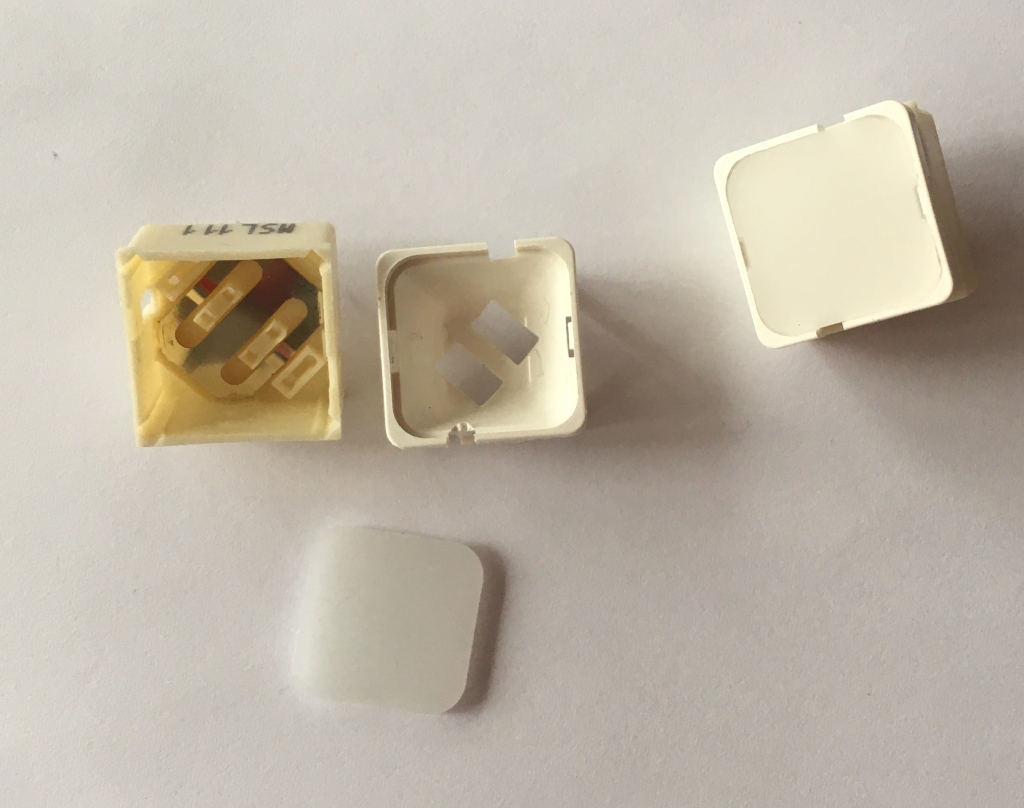
Preparing the hispaPanel (back panels)
HispaPanels are great. This board come with the frontal panel, an intermediate and a back panel. Due to the very type of the Encoder (with a squared base), the hole in the back panel interfered with the base of the Encoder, so I removed the excess plexiglass by using a Dremel. Similarly the fuse holder nut was beyond the available space so I did the same process for the fuse holder hole. To complete the preparation I removed (where necessary) the protective layer, this made the surface completely transparent, hence allowing an optimal backlight. All Hispapanels come with light (laser I think) cuts, so that this operation is easy and precise. The final result of the mid panel is shown below.


PCB
I purchased the great PSCockpit PCB, but had some problems integrating the buttons. Basically the problem was that the (internal) LED holes of the RAFI buttons do not match with the PCB holes.
For this reason I designed a PCB to suit my purpose. I did the job with easyEDA, which provides a great integration with the jlcpcb website. The board integrates seamlessly in the PSCockpit environment (I also took care to assign the same pinout as the original TWA board, so to avoid any hassle in the configuration). It has 16 I/O, with the common address switch that allows populating it in a daisy chain fashion with the MainBoard channels, a BIT led, to check whether the board is powered, and a backlight circuit, to highlight the TWA label.
In easyEDA I also had to design a custom component (the RAFI15H pushbutton, and its pinout, footprint, and 3D model). I have to think about the possibility to write a simple post with the lesson I learned throughout all the process. Bottom line is, jplpcb provides a great service and allows to have at a reasonable price, prototype PCBs, with also SMT service (surface mount)!
I finally chose to purchase the boards painted Black, so to reduce as much as possible any contrast with the rest of the panels, and case.


To interface the board with the other satellite boards, I used the standard 2.54 mm spacing Duponts connector. The board uses 12 I/O for the push buttons, and 2 for the encoder, hence a couple of spare I/O are left un-used, and are exposed to the user on the back of the PCB (Pin 3 and 4). It comes with a separated backlight circuit, with four LEDs to highlight the panel labels. The SMD resistors provide a way to obtain a rather clean board. The brightness (DIM) encoder is currently wired, even if in the simulator it is actually not implemented. The fuse holder, on the other hand is just for the sake of providing a mock-up of the real instrument, and is not connected in any (electrical) way to the rest of the boards components.

Soldering of components is pretty straight forward, with the possible exception of the 4 SMD LEDS (which are quite small). The fully assembled PCB results in a relatively compact assembly, which also provides a firm base to apply pressure to the pushbuttons.


3D printed case
In order to close the panel, and to secure it to the bottom of the Landing Gear panel through the L brackets, I modelled and 3D printed a back case. It’s form factor is the smallest possible, hence I let a couple of passing holes, to place the Dupont Connectors, and guarantee access to the spare pins. Being 1 mm thick, I stiffened the back through some ribs.

Assembly
Given the components mentioned above, the assembly was straightforward. Had to solder all the components, secure the fuse holder to the panel assembly, and finally solder the RAFI15H button with the panel in place (basically there is interference with the buttons, thus a bit annoying if something (like the backlight led) gets broken, but that’s it.
In order to hold the assembly and connect it to my Pit I used an L braket. I had to slightly modify it so to avoid any interference with the additional pins in back.


Integration with pscockpit
Following an advice of JShep, the developer of pscockpit, I assigned an empty channel to the TWA pcb, hence I had to give a bit of room to inside the ICP case 🙂
It is currently assigned to Channel 7, which was completely free. For the connections, as always, I provide separately the 5V, and GND, and then from the MainBoard I connect SDA, INT, SCL and GND (the reason I’ve two grounds, is to provide a common ground between the power supply and the MainBoard).
I will soon post an overview of the system, in the mean time enjoy!

Leave a comment